- One-dimensional LASER scanning for chip shooters (simple rectangular components), bi-dimensional vision for fiducial recognition and fine pitch placement, with or without oblique lighting (to qualify balls volume)
- Panel size from 2.6" x 2.6" to 11" x 16" (7cm x 7cm to 30cm x 40cm)
- Minimum 0.150" spacing required along the panel longest sides, free of components (could be provided by breakaway tabs or on the board itself)
- Three fiducials are required per panel. The usual format is a round 0.060" pad, centered in a 0.100" diameter solder mask free area.
Are required from the customer
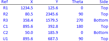
- Pick and place file. The usual format is .txt or .csv, showing one line per part designator or fiducial, with the geometric center of the part horizontal (X) and vertical (Y) coordinate in mil (or um), the part orientation (trigonometric angle of the vector stemming from the component center, along its axis, towards its distinctive point - pin 1, cathode, positive terminal, relative to the printed circuit board positive X axis), and the side (Top / Bottom) of the board the component is mounted on.
Pick and place file